During the course of The Modern Firepower Pinball Project, I've had to don many different caps. At various times I've been a researcher, analyst, designer, carpenter, painter, mechanical engineer, programmer, electrical engineer, project manager, financier and accountant. Now that I think about it, since I'm writing this blog I'm also the writer, photographer, and publicist. No wonder it has taken me over four years to get this far.
While all of the various tasks interest me (why else would I be doing this project), I understand that many pinball enthusiast, even diy hobbyist, just want to get to the good parts with videos of pinballs bouncing around. To those readers, fair warning, this is not that post! As if the title didn't already give that away.
This post is about circuit design and theory, and for most people I would expect this is an extremely boring topic. Even worse, I plan to share some technical details that many won't understand, including me. I have no formal education in electrical engineering, and I'm self taught outside of one class in college. As I share this information, I'll be presenting it in mostly layman terms, not EE terms, as this is how my brain works - I suppose I have a layman's brain. If you want to understand more about transistor design, usage and terminology, there's plenty of other resources on the web that cover those topics.
If you're a brave soul, you might find this post informative even if you don't have a real interest in electronic design. I found many forum posts online where people were trying to figure out how to get an LED-Wiz to control pinball solenoids. Well, this is how.
Now, to the topic at hand...
 |
| Rottendog Amusements makes modern replacement Driver Boards like this Williams WPC89/WPC-S replacement. While it is better than the originals, this board is still rather large, though it does handle more than just solenoids. |
One of the most important components in a pinball machine is the control circuit that sends power to the solenoids, moving the various mechanical assemblies like flippers, slingshots, and pop bumpers. The solenoids need lots of power to have enough oomph to move those heavy steel balls around the playfield. The Modern Firepower design will be using 50 volts, just like the Williams machines back in the day (not all pinball machine designs use or require 50v for the solenoids). In testing, I've measured some solenoids to be pulling more than 3 Amps of current when they fire, and at 50 volts that's over 150 watts of power! This is enough current to be deadly to humans, so safe design and handling is essential, and this amount of power far exceeds the electricity handling capability of computers and typical control circuits.
The solution is a power driver circuit board that bridges the gap. On one hand the power driver has to be capable of controlling the high voltage and amperage that is flowing to the solenoids, and on the other hand it has to respond to low powered control signals from the computing device while isolating it from the solenoid power. In pinball machines, this circuit board is typically referred to as the Solenoid Power Driver, and often it is integrated onto larger circuit boards with other types of circuits.
For Modern Firepower, the control signal will flow from a PC to a LED-Wiz over USB, then on to the Solenoid Power Driver sending power to the various solenoids on the playfield. The 50v power comes from a separate power supply transformer which will feed directly to the Solenoid Power Driver board.
 |
| Williams High Power Solenoid Circuit Schematic. 50v power flows directly to playfield coil (making the coil live) and from the coil to a TIP36C PNP transistor. A TIP102 NPN transistor is used to connect the TIP36C to the 2N5401 PNP pre-driver transistor that is controlled by the processor. There are 3 transistors, 5 resistors, and 1 diode in this circuit. |
My first prototype design for the Solenoid Power Driver was simply a copy of a couple William's solenoid power circuit designs commonly illustrated in the game manuals. The design used either two transistors (a "Low Power Solenoid Circuit") or three transistors (a "High Power Solenoid Circuit") for powering each solenoid, plus lots of resistors to make the transistors behave correctly. The circuit designs are complex, expensive to make, and require a large circuit board. I originally used these designs because they seemed compatible with the LED-Wiz, and it is easier to re-use someone else's design than to engineer from scratch.
 |
| Williams Low Power Solenoid Circuit Schematic. Basically identical to the High Power circuit, but with the TIP36C transistor removed. There are 2 transistors, 4 resistors and 1 diode in this circuit. |
At the time I didn't fully understand the difference between the "Low Power" and "High Power" circuits, and I didn't know which circuit design Modern Firepower would ultimately need. On a hunch, I guessed (wrongly) that the flippers were "High Power" devices and all the other solenoids were "Low Power". When I built my first prototype Solenoid Power Driver board, I included 4 "High Power" outputs, and 12 "Low Power" outputs. When testing time came, the high power circuit worked perfectly, but the low power circuits failed after only a few solenoid firings, sometimes dying even the very first time it was tested, regardless of what solenoid was being fired.
 |
| My first prototype Solenoid Power Driver. The TIP36C's are the four big transistors in back, which make up the 4 High Power circuits. This circuit board is rather large, about 12" long and almost 3" wide. Adding the necessary fuses to all circuits for safety, plus upgrading the 12 Low Power circuits to High Power, would more than double the size of this board. |
Lesson learned, all solenoids should be considered "High Power" devices, though I'm sure someone out there will correct me on this - from the hobbyist perspective, there's no need for a "Low Power" circuit, as the high power circuit can do it all and isn't any more expensive in my new design.
Earlier I mentioned that safety is a concern, and one element of the original Williams circuit scares the crap out of me. The design sends 50 volts to the ungrounded solenoids on the playfield, and when a solenoid is fired the Solenoid Power Driver switches on the ground connection. That means that the playfield is live with deadly voltage even when a solenoid isn't being used. This is called "low side switching". To address safety, pinball machines have a switch on the coin door so that when you open the door all power is shut down to the playfield. This is probably good enough, but I thought I could do better.
Instead of "low side switching", I wanted to implement "high side switching", which basically means only the Solenoid Power Driver board has power, the solenoids are un-powered and safe until a solenoid is fired. I wasn't sure it would work, but it seemed to me that by simply rearranging the circuit schematic I could accomplish this goal. Luckily, a quick test on my prototype board proved high side switching does work.
So this week I've been working on the Solenoid Power Driver circuit board design, upgrading all the circuits to the "High Power" design, incorporating high side switching, and adding in fuses for all the circuits. It was during this dreadful work that I had an 'A-Ha!' moment.
I realized that I get to play by a different set of design rules than Williams (and all other pinball manufacturers) simply because I'm using the LED-Wiz output driver boards to control not just my lights, but also the solenoids. The Williams circuit design I was borrowing was never tailored to the specific capabilities of the LED-Wiz. While a LED-Wiz cannot power a solenoid directly (that would be nice!), they are capable of working with up to 50 volts at 500 milliamps. The Williams circuit was (at least in my prototype) dropping the control voltage down to a USB compatible 5v and the current to probably less than a milliamp. The LED-Wiz is capable of so much more!
Looking at the Williams circuit design, I took a hacksaw to it and removed the 2N5401 PNP type pre-driver transistor, which the LED-Wiz didn't need, and then removed the TIP102 NPN transistor, which really just interfaces the TIP36C to the 2N5401. That left only the big daddy TIP36C transistor which directly switches the power to the solenoids. The idea looked promising, but would it work? I thought it would as long as the "base" side of the TIP36C transistor, which would now connect directly to the LED-Wiz, didn't need more than the LED-Wiz's 500mA maximum power limit in order to fully flip the switch to power the solenoid.
Conceptually, transistors work similarly to dimmers and amplifiers, in fact they are commonly used in audio amplifiers because they allow a small source signal to modulate a much larger output signal. The more power you send in, the more power you get out. Less control signal power in and the output is dimmed. When a transistor is providing less than full power, basically dimming the output, the unused power from the power supply is converted to waste heat in the transistor, which heats up the transistor, sometimes to the point of frying it. When the transistor is fully switched on, a state called 'Saturation', the transistor doesn't have to dissipate any waste electricity as heat, and it stays relatively cool. Using transistors in this manner, either off or fully saturated, is call switching, and this is the appropriate design for powering pinball solenoids. To correctly incorporate a transistor in a switching circuit requires the use of many parameters and formulas to determine the correct resistors to use in the circuit - design it wrong and the transistors won't reach saturation, shortening their life and reducing power to the pinball solenoids.
I reviewed the datasheet on the TIP36C, and observed that it's lowest hFE value is 10 (for switching circuit design, always go with the lowest published hFE value unless you know better). hFE can be thought of as the amplification factor, by which a source signal is multiplied to produce a much larger output signal; for example a 10 hFE means a 100mA source signal becomes a 1A output signal. You can also look at the amplification in reverse, determining that the control signal needs to be at least 1/10th of the load's max current in order to push the TIP36C transistor to saturation. Technically, the source signal could be higher than 1/10th, but once you reach saturation any increase in input power does not result in any additional output power.
For any EE's reading this, yes I know I'm grossly oversimplifying the technical details, but I warned I was using layman's terms.
Earlier I mentioned that some of the solenoids I tested were pulling more than 3 Amps of power. I don't know what the peak amperage could be for some solenoids, I've only tested a few, but for now I'm simply theorizing that 4 Amps is a peak. In case I'm wrong, I figured I should design this circuit to handle up to 5 Amps. Doing the math, using a TIP36C means the control signal has to be at least 500mA, 1/10th of 5A, in order fully switch the transistor. 500mA is right at the limit of the LED-Wiz published specs, so for a little headroom I dialed the control signal back (current is limited by the proper selection of resistors) to 450mA, which in theory should be enough to control a 4.5A solenoid with the TIP36C, possibly even higher since the hFE value is variable, and it increases with smaller loads (the TIP36C is capable of handling 25A loads, so pinball solenoids are smaller loads for it).
 |
| A prototype Solenoid Power Driver using only a TIP36C. The 500mA fuse at the top-right represents the LED-Wiz in the circuit. The eight 220 Ohm 2 Watt resistors were connected in series and parallel to create a test 110 Ohm 16 Watt resistor, and 16 Watts of heat dissipation still was not enough to keep them from overheating with prolonged use. While using a TIP36C technically worked, it is not the ideal transistor in this circuit design. |
I prototyped my new circuit design using my handy Radio Shack breadboard to test my theory. Instead of controlling the test circuit with an LED-Wiz, and potentially blowing it up, I used a fuse rated at 500mA to simulate the LED-Wiz, and manually switched the circuit on and off myself. I figured as long as the fuse didn't blow the control signal would be safe for the LED-Wiz too.
The circuit worked as anticipated, and the 500mA fuse didn't pop. I also tested with a 250mA fuse and it popped, proving that I was pulling somewhere between 250ma-500ma as I intended, so the math is working. Since both the voltages and the current are within the capabilities of the LED-Wiz, I confirmed that I can use this vastly simpler circuit design, with 1/3rd the components, and a much smaller circuit board.
It's not all good news, though, as the TIP36C transistor is not optimal in this new circuit. Since the TIP36C has such a low hFE amplification value of 10, reaching full saturation within the confines of the LED-Wiz's 500mA power limit really isn't possible. In my testing, the TIP36C was getting hot, proving that the transistor was not reaching saturation even with a relatively high 450mA control signal. The simplistic design rule of thumb to ensure saturation is to double the control signal's current just to play it safe, but 900ma is way too high for the LED-Wiz. Even worse, the resistor needed to set the current to just 450ma @ 50v will be dissipating about 20 watts of waste heat! Multiply that by 14 solenoids, and you now realize that this is completely unacceptable. So using a TIP36C in this application would result in a very inefficient circuit. In my testing, a 450mA control signal fried the resistor even when I scaled it up to 16 watts of capacity, and when I tried lowering the control current below 450ma the TIP36C's started dying on me - I lost three in testing.
| Fallen components that gave their life for pinball. In my testing, the TIP36C transistors died when the base current was too small, preventing transistor saturation and making them overheat, while the resistors burned up when the base current was too big. Unlike for Goldilocks, there wasn't a "just right" base current, forcing me to find a different transistor. |
So the options are to either use other transistors in line with the TIP36C (which is basically the original William's design) or find a better transistor to replace the TIP36C. I've found a new candidate that is both smaller in size and looks capable of doing the job. Transistors have a 'Safe Operating Area' that limits how much voltage and current you can send through it - the higher the voltage the lower the current it can safely handle. When you exceed the safe operating region the transistor eventually fails.
Going back to my original power driver test board, you'll recall that I tested both the Williams "High Power" and "Low Power" circuit designs, the primary difference being that in the low power circuit the TIP102 is exposed directly to the load. In my tests, the low power circuits failed pretty quickly after activating a solenoid just a few times, and I've always wondered why, because looking at the specifications for the TIP102 (100 volts max and 8 Amps continuously with a 15 Amp peak) , this little transistor seemed plenty capable. I now have the answer, as it was operating well outside the Safe Operating Area. The TIP102 is easily capable of handling both 50v and 4A, just not at the same time. At 50v, the TIP102 can't even safely handle 1A, and at 4 Amps it maxes out at 20 Volts. It's no surprise the TIP102's died so quickly in my "Low Power" circuit tests.
 |
| TIP102 Safe Operating Area chart: Green area is safe for pinball solenoid usage. The blue lines identify 4A @ 50V, which is the load I'm seeing in my Pinball build. Since the TIP102 can only handle 600mA at 50V, it is unsuitable for this load. |
The TIP36C is definitely more capable than the TIP102, as at 50V it can handle a little more than 1 Amp, and at 4 Amps it can handle 30V.
If you've been paying attention and understanding the math so far, you might be scratching your head wondering why the TIP36C was chosen by pinball manufacturers for use in 50V circuits, as it seems pretty obvious it is not being used in the Safe Operating Area. I honestly have no idea, and I was very shocked when I analyzed the chart.
Perhaps the voltages and currents seen by the TIP36C in a real pinball machine are a bit less than I've calculated, and the pulse time may also be shorter than the 100-200 ms I'm anticipating. Another consideration is that in pinball duty the transistor gets sufficient cool-down time between firing solenoids.
Regardless, as long as I'm going to replace the TIP36C in my circuit design, I might as well find a more capable transistor.
 |
| Surprisingly, for pinballs that use 50v power supplies, even the TIP36C is operating outside of it's Safe Operating Area. I was very surprised by this, since the TIP36C is so commonly used by pinball manufacturers. The TIP36C can handle just over 1A at 50V, so while it is better than the TIP102, I would still expect these to burn out regularly. |
My new transistor choice is capable of supporting 50v at 4 Amps (both values slightly higher than I'm expecting the circuit to see), but only in pulsed operation of less than 100ms. In constant DC operation (always on), the limits are lower than I spec'd, but superior to the TIP36C. The usage model for Pinball is closer to pulsed operation. My software is currently pulsing solenoids for 200ms, a value which seemed to be a good in preliminary tests (I have this configurable per solenoid to fine tune the game), so I'm hedging a bet that this transistor will be on the fringe of the Safe Operating Area. The only solenoids that fire longer than 200ms are the flipper, which fire as long as you hold the flipper button, but the flippers I'm using are the older design that have dual coils: a high-power lift coil, and a low power hold coil. When in hold position, the low power coil won't pull enough current to hurt the transistor.
 |
| While technically the 4A @ 50V load is outside the safe operating region of the new transistor too, it is significantly better than the TIP36C. The yellow area on this chart represents a pulsed load area that is probably safe for pinball use. Since the solenoids are actually pulling less than my 4A design max, they do fall within the yellow area. This transistor can handle 3A @ 50V in pinball duty, 3x better than the TIP36C, and 5x better than the TIP102. |
The other notable attribute of this new transistor is that it is a Darlington Pair, which basically means it is two transistors joined together inside one transistor case, and the hFE ratio is a magnitude higher. How high? This particular transistor's hFE will be about 1000 in this application, versus the measly 10 of the TIP36C. That means to reach saturation while driving a 4 Amp solenoid, the control circuit to the LED-Wiz only needs about 4 milliamps! Now, that's efficient! Instead of just doubling the control current to 8mA to ensure saturation, I have enough headroom to quadruple it to 16mA to ensure circuit always fully saturates the transistor. 16mA is well within the capabilities of the LED-Wiz, and only wastes about 1/2 watt of power on the controlling resistor.
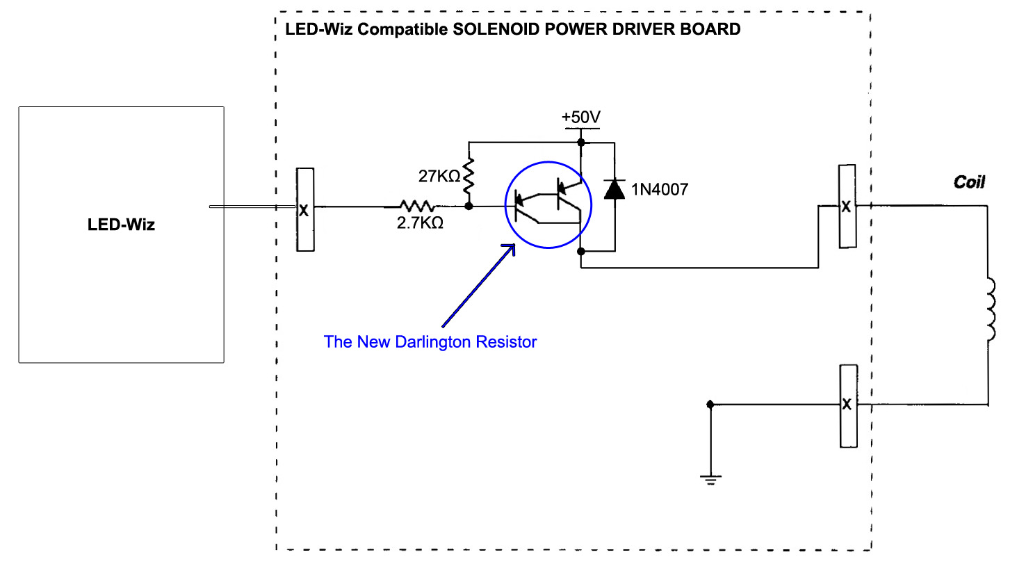 |
| Compared to the Williams High Power Circuit, this new LED-Wiz optimized circuit is much simpler, with only one transistor, two resistors, and a diode. Not only is the schematic smaller, but the physical size of the new transistor is much smaller than the TIP36C, so the resulting circuit board should be very compact. |
I'm ordering up the new parts today. I don't want to reveal the chosen parts at this time, as the circuit design is still just theory. I want a proven solution before I advise other people to use this approach.
I'll report back soon with updated test results and images of the final circuit board design, showing off the new smaller size.
the 1N4007 should be connected between the coil leads, this circuit as is does not produce any flywheel effect.
ReplyDeleteHey Rolando, you're absolutely right. I have diodes on all coil leads on all my pinball solenoids. It's not shown in the power driver schematics above, which were all lifted from old Williams documentation. I didn't think to add that detail to the schematics, thanks for pointing this out. Regardless of power driver design, it is best practice to have a diode across the coil leads.
ReplyDelete